| |
In 1958
the Low Pressure (LP) boilers were still in situ but when I returned in
the summer of 1959 after eleven months at the apprentice training school,
East Yelland, they had been removed. The remaining installed boiler
capacity was sufficient for the installed turbine capacity with just a
minor adjustment. A pressure
reducing range between the HP boilers and LP turbines had been installed.
There was already a steam pressure reducing range between the MP boilers and LP turbines. |
| |
|
| |
The LP Stirling boilers constructed between 1920 and 1923 as
part of the AC station were numbered 5,6,7 & 8 and the
steam turbines nos. 3 & 4. Boilers 1 to 4 formed the original DC
generating station. Boilers 5-8 with an evaporation rate of 25,000
lbs/hr were chain grate with a
single Induced Fan per pair of boilers which drew the air for combustion through the moving
grate. Coal to the grate was fed via hoppers and chutes but largely
controlled by manual labour and all ash handling was via manually hauled
trolleys on a system of rails - an horrendous dark and sulphurous atmosphere - dirt
was not the word for it. There are no records regarding Boilers 1 to 4 but
they will have been entirely hand fired - a very manual process. |
| |
|
| |
The boiler feed pumps were neat small steam
turbines which were a real piece of machinery requiring virtually no
maintenance. Cooling water to the turbine condensers was fed from the
Number 1 Pump house on the River Teign. The cooling water was returned
further down stream to the River Teign. |
| |
|
| |
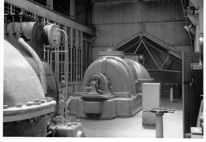
The turbine operating steam pressure was 150 psi
with the boilers and steam range target being 165 psi at 540 deg F (282
deg C). The turbines were
3000 rpm British Thomson-Houston (BTH) and rated at 3750 kw connected at 11,000
volts to the cellular switchboard. In the picture below the Electrical Maintenance
workshop was behind the windows on the left. I suspect this area included
the first control room and below this the 11kv cellular switch gear. |
| |
|
| |
The roof frames in the distance covered the two 400
kw DC
Rotary Convertors and the 500 volt DC Switchboard together with a 500 volt
600 ampere hour battery bank. |
| |
|
| |
 |
| |
The LP Turbine Hall - Generators 3 &
4 - Exciter and Alternator end |
| |
|
| |
 |
| |
|
| |
 |
| |
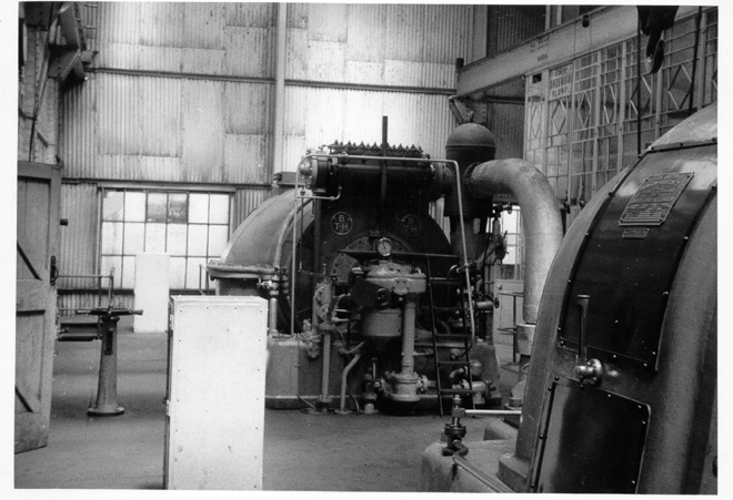
HP Steam end - Governor Gear and
Speeder motor |
| |
|
| |
Following the removal of the LP boilers the
basement area was converted into a Civil Defence Regional shelter - a serious
concrete structure with is own diesel generator and air conditioning. It
was never used in anger but provided a base for tools and equipment in the
event of a civil emergency. |
| |
|
| |
|